
Dust mite controller
Household vacuum cleaner Sweeping robot
Industrial dust collection equipment Micro dust detector
Description
Based on the principle of optical shadow detection, the micro dust sensor M3-M series is optimized for mites making it is possible to accurately measure the mites and particles in dust mite controller, vacuum cleaners, sweeping robots and other equipment, , and finally give the accurate mass concentration.
Features
Emission circuit board, receiving circuit board and main control circuit board are separated, which can be used more flexibly in the user's structure
It can be used to accurately measure particles over 20μm under high wind speed, and it is optimized for mites
The data response time is 1000 ms
Range of measurement is 0~1000 mg/s
Low power consumption, working current is only 30mA
The serial port output mode with verification can provide accurate data
Working Principle
M3-M series products place the optical transmitter and optical receiver at 180 ° ± 10 °. The receiver receives the light from the transmitter to generate photocurrent, forming a signal. When there are mites or particles passing through, due to the principle of optical shadow, the light intensity received by the receiver changes, forming a changing pulse. Through filter amplification, MCU processing, the mites or particles of different sizes can be distinguished and count according to the size of the pulse. Finally calculate the mass concentration of particles.
Specification
|
Specification of product |
|
|
Range of measurement |
0~1000 mg/s |
|
Resolution |
1 mg/s |
|
Minimum particle size |
20μm |
|
Response Time |
1000 ms |
|
Data Output |
UART @ 3.3V |
|
the time interval of serial output |
1000 ms |
|
Power Supply |
DC 5V±0.1V, ripple wave<100mV |
|
Working Current |
≤ 30mA |
|
Operationtemperature/humidity |
-10℃~65℃ / 0~98% RH(non-condensation) |
|
Storage temperature |
-20℃~80℃ (non-condensation) |
|
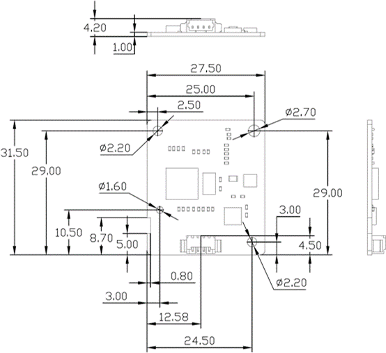
Size |
Main control circuit board: 27.5*31.5*1 mm (Only PCB) |
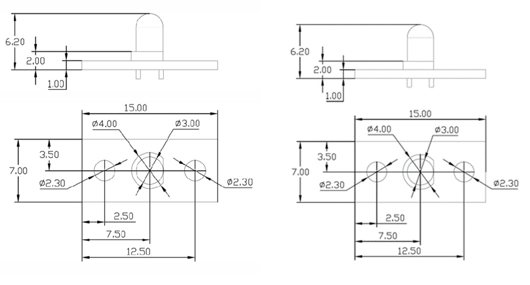
|
Emission circuit board: 7*15*1 mm (Only PCB) |
|
|
Receiving circuit board: 7*15*1 mm (Only PCB) |
|
|
Conducting wire:100 mm |
|
|
Installation requirements |
Theemissioncircuitboardshouldremain180°againstthe receiving circuit board |
|
Life Time |
>5 years |
Dimensions and Connector
Dimensions (Unit mm, tolerance ±0.2 mm)
Dimensions of main control circuit board
Dimensions of emissioncircuitboard Dimensions of receiving circuitboard
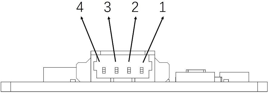
I/O Connector Pinout
|
NO. |
Pin |
Description |
|
1 |
VCC |
Power Supply |
|
2 |
GND |
Ground |
|
3 |
RXD |
UART Digital Input |
|
4 |
TXD |
UART Digital Output |
Connector
|
Item |
Model |
Quantity |
Pitch |
|
Connector |
4PIN-1.25-D |
1 |
1.25 mm |
Communication Protocol
o The data is all hexadecimal data. For example, [46] for decimal“70”
o [XX] represents single-byte data (unsigned or signed,0~255)
o For double data, high byte is in front of lowbyte
1) Setting of Serialport
|
Setting Item |
Setting |
|
Baud Rate |
9600 bps |
|
Data Bits |
8 |
|
Parity |
None |
|
Stop Bits |
1 |
|
Flow Type |
None |
2) DataPacketofProtocol
|
NO.(HEX) |
Data NO. |
Data |
Data Description |
|
0x00 |
Header 1 |
0x42 |
Frame header |
|
0x01 |
Header 2 |
0x4D |
|
|
0x02 |
Frame Length igh byte |
0xXX |
Frame Length=2*13+2(Data+Check) |
|
0x03 |
Frame Length low byte |
0xXX |
|
|
0x04 |
Data 1 high byte |
0xXX |
Reserved |
|
0x05 |
Data 1 low byte |
0xXX |
|
|
0x06 |
Data 2 high byte |
0xXX |
Reserved for test |
|
0x07 |
Data 2 low byte |
0xXX |
|
|
0x08 |
Data 3 high byte |
0xXX |
Reserved (0) |
|
0x09 |
Data 3 low byte |
0xXX |
|
|
0x0A |
Data 4 high byte |
0xXX |
Reserved |
|
0x0B |
Data 4 low byte |
0xXX |
|
|
0x0C |
Data 5 high byte |
0xXX |
Concentration of total micro dust Unit: mg/s |
|
0x0D |
Data 5 low byte |
0xXX |
|
|
0x0E |
Data 6 high byte |
0xXX |
Reserved (0) |
|
0x0F |
Data 6 low byte |
0xXX |
|
|
0x10 |
Data 7 high byte |
0xXX |
Reserved (0) |
|
0x11 |
Data 7 low byte |
0xXX |
|
|
0x12 |
Data 8 high byte |
0xXX |
Reserved (0) |
|
0x13 |
Data 8 low byte |
0xXX |
|
|
0x14 |
Data 9 high byte |
0xXX |
Reserved (0) |
|
0x15 |
Data 9 low byte |
0xXX |
|
|
0x16 |
Data 10 high byte |
0xXX |
Reserved (0) |
|
0x17 |
Data 10 low byte |
0xXX |
|
|
0x18 |
Data 11 high byte |
0xXX |
Reserved (0) |
|
0x19 |
Data 11 low byte |
0xXX |
|
|
0x1A |
Data 12 high byte |
0xXX |
Reserved (0) |
|
0x1B |
Data 12 low byte |
0xXX |
|
|
0x1C |
Data 13 high byte |
0xXX |
Reserved (0) |
|
0x1D |
Data 13 low byte |
0xXX |
|
0x1E |
Check high byte |
0xXX |
Check= Header 1+ Header 2 +……+ Data 13 low byte |
|
0x1F |
Check low byte |
0xXX |
User Attention
o Makesurethattheemissioncircuitboardandthereceivingcircuitboardare connected to the main control circuitboard.
o During installation, make sure that the optical transmitter and the optical receiver are facing each other and aligned with the cavity to be measured, and the angle between the transmitter and the receiver is 180 ° ± 10°.
o The distance between the optical transmitter and the optical receiver shall be less than 60mm.
o The power supply shall not exceed the specified power supply voltage of the product, so as to avoid damaging the product
o The ripple of power supply should be less than100mV,otherwise the output data will bewrong
o This product has no reverse connection protection. Do not reverse connect the power supply to avoid damaging theproduct
o Do not connect other output interfaces with signals exceeding the withstand voltage to avoid damaging the product.
o The product shall be used as far away from the electromagnetic radiation source (high frequency and high voltage generating device, etc.) as possible to avoid the interference of electromagnetic radiation on themeasurement.
o When in use, the cavity to be tested shall be completely dark as far as possible to avoid the influence of external light on themeasurement.
o During use, large or irregular vibration shall be avoided to avoid the influence of vibration onmeasurement.
o The emission circuit board and the receiving circuit board shall be fixed as far as possible to avoid the influence of looseness and shaking on themeasurement.